
Typing on a cheap membrane keyboard is like driving a car whose shock dampers aren’t working right; it works, but you can feel every rough bump. When you use a custom mechanical keyboard and feel its thoughtful, tuned feedback, going back to a regular laptop keyboard feels empty.
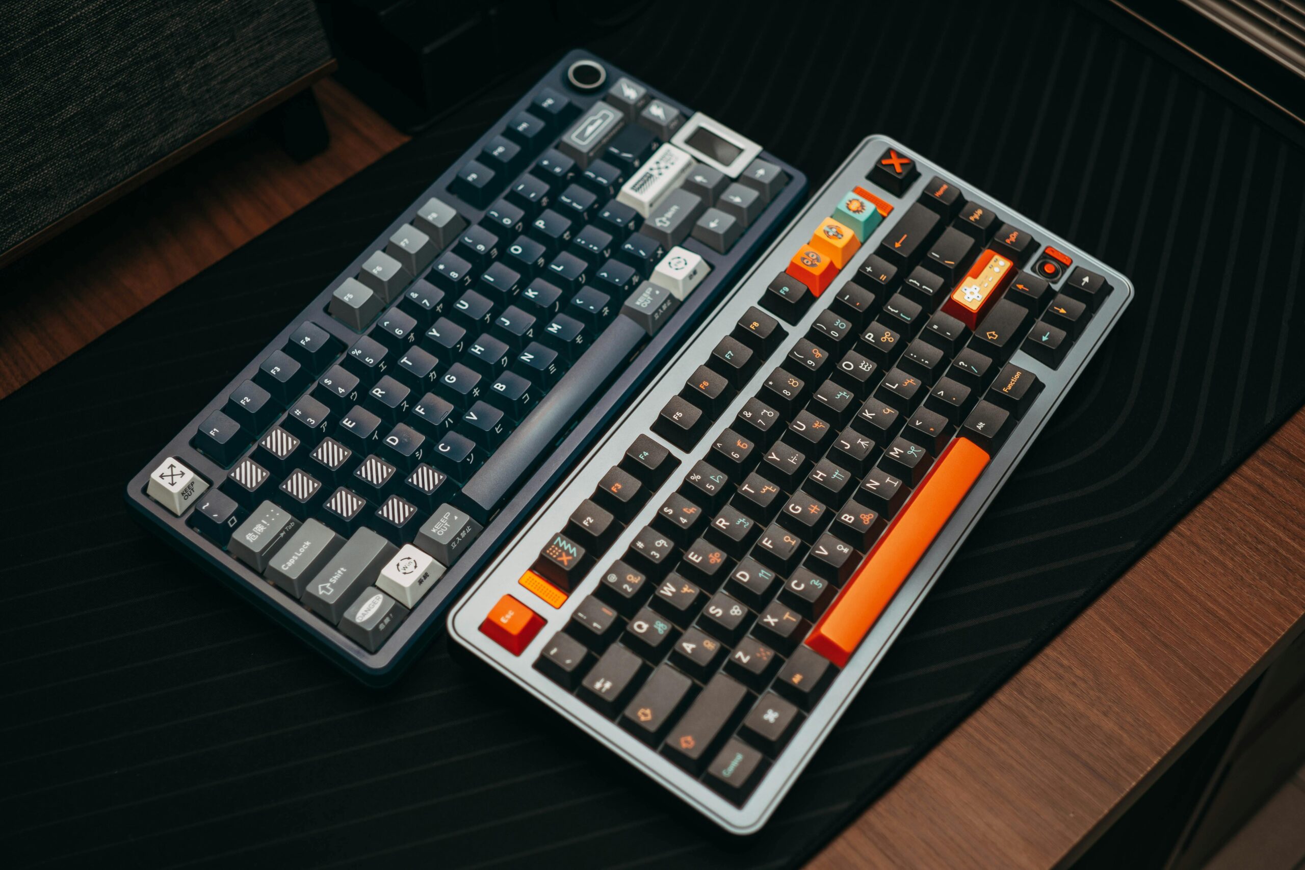
Making mechanical keyboards is both a proper engineering exercise and a tactile art project. The sound signature, the stiffness of the keys, and the way they fit on your desk are all up to you.
Putting together a keyboard from separate parts lets you make the exact tool you need, whether you’re a programmer who wants to keep your fingers from getting tired or a gamer who wants to make the best use of workspace for low-sensitivity mouse swipes.
Defining Your Form Factor and Footprint
Before sourcing individual switches or keycaps, you have to determine your layout. This dictates the printed circuit board (PCB) and case you will buy. Keyboard sizes are categorized by the percentage of a traditional 104-key board they represent.
- Full-Size (100%): Measures roughly 17 inches across. It includes the number pad, navigation cluster, and function row. While excellent for data entry, its width forces your mouse hand further outward, which can cause shoulder strain during long sessions.
- Tenkeyless (TKL / 80%): Sits at about 14 inches wide. It drops the number pad but keeps the arrow keys and function row. This is the most common transition layout because it requires minimal muscle-memory retraining while freeing up significant desk space.
- 75% and 65%: A 75% board compresses the TKL layout by stacking the navigation keys vertically. A 65% board (typically 12 to 13 inches wide) removes the function row entirely but crucially retains dedicated arrow keys.
- 60%: At roughly 11.5 inches, this layout drops arrow keys entirely, hiding them behind a programmable “Fn” layer. It offers maximum mouse clearance but requires adaptation.
For your first build, a 65% or 75% layout represents the best physical compromise. You maintain the essential arrow keys for text navigation without allowing the board to dominate your workspace.
The Core Components: Trade-Offs and Tolerances
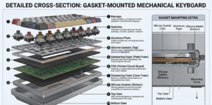
A mechanical keyboard is a layered sandwich of electronics and dampening materials. Understanding how these layers interact is what separates a hollow, rattling board from a premium, muted one.
1. The PCB: Hot-Swappable vs. Soldered
The Printed Circuit Board registers your keystrokes. You have two primary choices for attaching your switches.
A hot-swappable PCB features specialized sockets that allow you to plug in and pull out switches using a metal extraction tool. For beginners, this is highly recommended.
It allows you to experiment with different switch types without touching a soldering iron, and if a switch fails, you pull it out and push a new one in.
The downside is that hot-swap sockets dictate a fixed layout, so you cannot usually split the spacebar or shift keys.
A soldered PCB requires you to melt metal wire to physically bind the switch pins to the board. While this demands more tools and patience, it creates a highly durable connection and allows for exotic, non-standard key layouts.
2. Mounting Styles and Acoustic Signatures
How your plate and PCB attach to the external case drastically alters the sound and typing feel.
- Tray Mount: The cheapest and most common entry-level method. The PCB screws directly into standoffs on the bottom of the case. This creates a stiff, uneven typing feel because keys located directly over the screws feel rock-hard, while keys in the center of the board flex. It often produces high-pitched, metallic pinging.
- Top Mount: The mounting plate is screwed into the top half of the case. This results in a very consistent, firm typing feel across the entire board and typically yields a sharp, “clacky” sound profile.
- Gasket Mount: Enthusiasts favor this approach. Strips of foam, rubber, or silicone are placed between the plate and the case, isolating the typing assembly from the hard outer shell. This absorbs the shock of bottoming out your keys, reducing finger fatigue and producing a deep, rounded acoustic profile commonly referred to as “thocky”.
3. Key Switches: Linear, Tactile, and Clicky
Switches dictate the physical resistance and feedback of your typing. Inside each switch is a spring, a moving stem, and metal leaves that complete a circuit.
- Linear Switches: The stem travels straight down with uniform resistance until it bottoms out. Because there is no bump, they are incredibly smooth and favored for rapid, repetitive keystrokes in gaming.
- Tactile Switches: The stem features a physical protrusion that pushes against the metal leaf, creating a distinct “bump” midway through the press. This confirms the key has been actuated before you fully bottom out the spring. While Cherry MX Browns are the standard baseline, enthusiast switches like the Zealio 65g utilize different spring weights and steeper stems to create a much sharper, refined tactile bump.
- Clicky Switches: Similar to tactiles, but they include a mechanism like a click jacket or a click bar—that snaps downward to produce a sharp, audible sound. They are highly satisfying but generally too loud for shared office environments.
If you are unsure, tactile switches are an excellent starting point for heavy typists, while linear switches are preferred for gaming.
4. Keycaps: Material and Profile
Keycaps are your primary physical touchpoint. They are typically molded from ABS or PBT plastic. ABS allows for incredibly vibrant colors but tends to polish and shine over time from the oils on your fingers. PBT is denser, resists shining, and provides a textured, dry feel.
Look for double-shot keycaps. Instead of printing ink onto the surface, the legend (the letter) and the outer shell are molded from two separate pieces of plastic that are fused. Double-shot legends are physically integrated into the cap and will never fade.
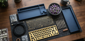
Essential Tools and Budgeting
You do not need an entire workshop, but utilizing the correct tools prevents permanent damage to your components.
| Tool | Purpose | Estimated Cost |
|---|---|---|
| Precision Screwdrivers | Case assembly: magnetic tips prevent lost screws inside the case. | $15–$30 |
| Wire Keycap Puller | Removes keycaps cleanly. Avoid cheap plastic ring pullers, which scrape the sides of your keycaps. | $5–$10 |
| Switch Puller | Extracts hot-swap switches by compressing their plastic tabs. Metal pullers prevent bending the fragile copper pins. | $8–$15 |
| Krytox 205g0 Lube & Brushes | The industry standard for lubricating linear switch stems and stabilizer housings. | $10–$20 |
| Dielectric Grease | A thicker lubricant strictly used for coating metal stabilizer wires to eliminate rattling metal noises. | $5–$10 |
| Anti-Static Tweezers | Used for handling small springs and safely testing the PCB contacts. | $4–$10 |
If you are opting for a soldered build, you will also need a temperature-controlled soldering iron, flush cutters, and a solder sucker.
Step-by-Step Implementation Guide
Building a keyboard takes anywhere from two to four hours, depending on whether you are manually lubricating your switches.
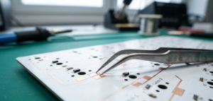
Step 1: Bench-Test the PCB
Never assemble your keyboard without checking the electronics first. Plug the bare PCB into your computer using a USB cable. Open an open-source configuration tool like VIA or QMK and navigate to the key tester.
Take your metal tweezers and bridge the two copper sockets for every single key. If the key registers on your screen, the socket is functional. If not, contact the vendor for a replacement before you build.
Step 2: Prep and Lube the Stabilizers
A keyboard is only as good as its spacebar. Unlubricated stabilizers produce an aggressive, cheap-sounding rattle. Using a small brush, apply a light coat of Krytox 205g0 to the inside of the plastic stabilizer housings.
Next, dip the ends of the metal stabilizer wire into your thick dielectric grease. Snap the wire into the housing. This thick grease acts as a shock absorber, silencing the metal-on-plastic impact. Screw or clip these directly into the PCB.
Step 3: Mount the Switches
Place your mounting plate over the PCB. If you are using a hot-swap board, align the two copper pins on the bottom of the switch with the sockets on the PCB, and press straight down. Do not force it. If you feel harsh resistance, stop. Pushing at an angle will crush the copper pins, ruining the switch.
Real-World Case Study: The Soldering Temperature Trap
If you choose a soldered PCB, environment matters. I once attempted to solder a KBD75 board outside on a summer evening to avoid inhaling flux fumes. I had my iron set to 400°F, but the evening breeze rapidly cooled the tip. The solder melted just enough to look secure, and the keys tested fine initially. By the next morning, the metal had contracted, breaking the weak electrical connections (cold joints). Always solder indoors in a well-ventilated space, keeping your iron consistently between 315°F and 350°F.
Step 4: Software Configuration
Using VIA, you can remap any key without writing code. Because smaller boards (like 60% layouts) lack physical function keys, you rely on “Layers”.
For example, you can program VIA so that holding the Caps Lock key activates Layer 1.
On Layer 1, your WASD cluster becomes your arrow keys, and your number row becomes F1-F12.
This allows your hands to perform complex navigation without ever leaving the home row.
Common Mistakes Checklist
- Ignoring bent switch pins: Always inspect the bottom of a switch before inserting it into a hot-swap socket. Attempting to force a bent pin will tear the hot-swap socket cleanly off the PCB.
- Over-lubricating switches: Using too much Krytox 205g0 will pool inside the switch housing. This destroys the tactile bump on tactile switches and makes linear switches feel sluggish and sticky. Less is more.
- Using plastic tweezers near a soldering iron: If handling components during a soldered build, ensure you use ESD-safe metal tweezers. Plastic tips will melt instantly upon accidental contact with the iron.
- Buying incompatible parts: Ensure your PCB, plate, and case are explicitly made for each other. A 65% PCB from one vendor will rarely fit a 65% case from another due to different USB port placements and screw hole alignments. Buying a bundled “kit” avoids this entirely.
Final Thoughts
When you build a mechanical keyboard, your connection with your main tool for work changes. You no longer have to get used to typing on a standard piece of plastic; instead, you design a device that fits your physical needs, typing speed, and personal style.
If you choose an easy-to-work-with layout, buy good stabilisers, and test your PCB and parts, you can be sure that the final result will last longer and work better than any store-bought option. You can choose a style, find a good kit, and then enjoy typing on something you built yourself.